


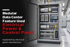


Factory-prewired electrical panels can reduce the amount of electrical assembly required during modular building installation. Their value depends on how clearly the factory work connects with the work remaining at the site.
A panel may leave the factory fully wired internally while still requiring incoming supply connections, outgoing field wiring, grounding connections and installation verification. Another package may include labeled cable assemblies or wiring already installed within the building module.
Both may be described as “prewired,” although their delivery scopes are substantially different.
For modular building manufacturers, contractors and procurement teams, the first task is to define what is prewired, where the supplied wiring ends and who completes each remaining connection.
“Factory-prewired” describes work completed before shipment. It does not, by itself, define the complete electrical package.
The specification should identify the physical boundary of the supplied assembly and the condition in which each interface will be delivered.
This scope covers the connections completed between components within the panel.
Depending on the panel’s function, it may include connections between protective devices, distribution blocks, power supplies, contactors, controllers and terminal blocks.
The incoming supply and outgoing field connections may remain unconnected until installation.
A clear scope description would state:
Panel supplied with internal wiring completed. Incoming supply and outgoing field connections are to be completed by the designated installer.
The drawings should identify the terminals or connection points where factory wiring ends.
A panel may include outgoing terminals, designated cable tails or other prepared connections.
These arrangements require more detail than “outgoing wiring included.” Specify the connection type, conductor requirements, identification and intended destination.
For cable tails, define their length and the reference point from which it is measured. Also identify how unconnected ends will be protected during transport.
Some projects include separately supplied or panel-connected cable assemblies.
Their specification should identify:
A cable assembly is not automatically suitable for every installation route or module arrangement. Its selection must reflect the electrical and mechanical conditions of the project.
The scope may extend beyond the panel to wiring installed within a prefabricated room, equipment module or building section.
This can include lighting circuits, receptacle circuits or connections to installed equipment.
Identify whether the panel supplier, module manufacturer or another contractor performs that work. The inspection and documentation boundaries should follow the actual work performed.
Connections between building modules form a separate interface.
They may use field terminations, junction boxes or specifically selected connector systems. Define the connection method, access, identification and installation responsibility.
Do not assume that a panel supplied with internal wiring includes the connections between modules.
A useful enquiry separates each wiring layer instead of treating the building as one undefined package.
| Supply layer | What to define | Typical remaining interface |
|---|---|---|
| Panel internal wiring | Connections completed inside the supplied panel | Incoming and outgoing connection points |
| Prepared outgoing connections | Terminals, tails or designated connection provisions | Connection to module or site wiring |
| Cable assemblies | Cable and termination scope at both ends | Routing, support or final connection |
| Module wiring | Circuits installed within a building section | Supply and inter-module connections |
| Inter-module wiring | Connections joining separate modules | Final assembly and verification at site |
These are scope categories, not a fixed division of responsibility. A supplier may provide several layers, but the contract should state which ones are included.
A quotation should make both supplied work and remaining work visible.
For example:
| Item | Scope statement |
|---|---|
| Internal panel wiring | Included according to approved drawings |
| Incoming supply cable | Supplied and installed by others |
| Outgoing cable assemblies | Included only where listed in the cable schedule |
| Cable routing within modules | Responsibility assigned to the module manufacturer |
| Inter-module connections | Completed at site by the designated contractor |
| Final installation verification | Defined in the project inspection and commissioning scope |
Avoid leaving an interface unassigned because it sits between two suppliers.
Modular buildings can contain different types of electrical assemblies.
A distribution panel supplying lighting and receptacles has a different function from a control panel operating pumps, ventilation equipment or building services.
The RFQ should state what the panel does before selecting its construction and applicable requirements.
Define the supply system, incoming arrangement, branch circuits and protective devices.
Provide a circuit schedule identifying the loads served by the panel, including any spare circuits and future provisions.
Where a load center is used, the specification should also establish the main configuration, bus rating, branch spaces and permitted breaker types.
Define the controlled equipment, operating sequence, inputs, outputs and external interfaces.
A control panel may require signals from devices installed in another module or at the final site. Those interfaces should be identified before the internal wiring is finalized.
Factory simulation can support functional checks, but it does not establish the behavior of equipment that has not yet been connected.
A supplied package may contain both distribution and control functions.
Identify the functional boundaries, protective arrangements and external connections. Do not select an applicable product standard solely from the general description “electrical panel.”
The destination market and actual assembly scope must guide the compliance review.
A modular building may be manufactured in one country and installed in another.
The electrical specification must address the installation destination, rather than assuming the factory’s usual configuration is suitable.
Provide:
These inputs should be consistent across the single-line diagram, panel schedule and module drawings.
The supplied panel, module wiring and completed building may have separate compliance and acceptance requirements.
State the required certification or conformity scope for the panel. Then identify the requirements applying to the building module and final installation.
Certification of one supplied assembly does not automatically establish acceptance of all connected wiring or the completed building.
Likewise, a factory inspection record should identify the scope inspected rather than imply that site work has already been verified.
The project needs a named owner for each interface.
The same company may perform several tasks, but the responsibility should remain explicit in the project records.
| Activity | Responsibility to assign |
|---|---|
| Electrical design and system inputs | Project designer or designated engineering team |
| Panel manufacture and internal wiring | Panel supplier |
| Wiring installed within modules | Module manufacturer or appointed electrical contractor |
| Cable assembly manufacture | Named supplier |
| Transport disconnections | Party preparing the module for shipment |
| Site reconnection | Designated installer |
| Installation verification | Responsible inspection or commissioning party |
| Final settings and functional commissioning | Named project team |
| Authorization to energize | Responsible site authority |
At release, each connection should have a clear status.
For example:
These statuses help the receiving team understand what must happen before the installation can proceed.
The scope becomes practical when the drawings and schedules identify the same interfaces.
A useful initial package includes:
| Document | Purpose |
|---|---|
| Single-line diagram | Defines the supply and distribution arrangement |
| Panel or circuit schedule | Identifies outgoing circuits and protective devices |
| Wiring diagrams | Shows internal and external connection points |
| Module layout | Establishes panel position and cable routes |
| Cable schedule | Identifies cables, destinations and termination scope |
| Interface schedule | Records connection boundaries and responsible parties |
| Inspection and handover requirements | Defines the records needed for release and site work |
Detailed production information can develop during engineering, but the supply boundary should be established before quotations are treated as comparable.
A factory-prewired package is most useful when its interfaces are deliberate and documented. The next step is to define those interfaces in detail: incoming power, outgoing circuits, neutral and grounding connections, terminals, cable routes and the points that will be disconnected for transport.
A factory-prewired panel connects to a wider electrical installation. Its incoming supply, outgoing circuits, protective grounding and control connections must agree with the module design and the final site arrangement.
An interface schedule helps turn those requirements into identifiable connection points.
Each interface should state what connects, where it connects, how it is identified and who completes the connection.
Use a common schedule across the panel drawings, cable documentation and module layout.
| Interface field | Information to record |
|---|---|
| Connection ID | Unique identifier used across project documents |
| Origin and destination | Equipment, panel, module and connection point |
| Electrical function | Power, control, communications or protective grounding |
| Electrical requirements | Relevant voltage, current, circuit and protection information |
| Connection method | Terminal, lug, junction box or specified connector |
| Cable requirements | Construction, conductor arrangement and length |
| Delivery condition | Connected, disconnected, separately supplied or field-terminated |
| Responsibility | Party supplying, installing and verifying the connection |
| Drawing reference | Applicable document and revision |
Avoid relying on cable color or physical proximity as the only means of identification.
The panel’s incoming connection must suit the electrical system at its destination.
A factory test supply may differ from the final site supply. The approved specification should identify the intended installation conditions.
Record the voltage, frequency, phase and wire arrangement, together with the required incoming current and upstream protective arrangement.
Identify whether the panel includes a main protective device or receives power through incoming terminals. The specification should separately establish any local disconnecting requirement.
If the available fault current or upstream device has not been confirmed, identify the responsible party and the point at which that information is required.
“Bottom entry” does not establish a complete incoming interface.
Provide the conductor material, size, quantity and intended route. Confirm terminal suitability and the space needed to bring the conductors to the connection point.
The layout should account for:
Show the designated entry area on the approved drawing so site openings do not conflict with internal equipment or wiring.
The panel schedule and module wiring drawings should describe the same circuits.
A change in room layout, installed equipment or module boundaries can alter cable destinations and routing. Review those changes before the panel wiring and cable assemblies are released.
An outgoing schedule should include the circuit designation, load, protective device, conductor requirements and destination.
| Circuit information | What to confirm |
|---|---|
| Circuit ID | Consistent identification across drawings and labels |
| Load | Equipment or area supplied |
| Protective device | Type, poles, rating and required functions |
| Conductors | Specified construction and sizes |
| Destination | Module, equipment and termination point |
| Supply scope | Factory-installed wiring, supplied cable or field wiring |
| Spare provision | Installed spare circuit or defined future provision |
Distinguish an unused breaker position from a complete spare circuit with terminals and wiring.
Confirm the mounting position, enclosure depth, door operation and access within the module.
Cable lengths should follow the intended route, including supports, transitions and termination allowances. A straight-line distance between the panel and equipment is rarely sufficient for cable manufacture.
Identify the measurement reference points and any permitted adjustment allowance.
Neutral and protective grounding arrangements must follow the electrical system and the role of the supplied assembly.
Do not decide bonding solely from whether the panel includes a main breaker.
Specify which neutral and grounding bars, terminals and bonding connections are supplied within the panel. Then identify the external connections completed by the module manufacturer or site installer.
The interface review should cover:
Shipping or joining metal modules does not, by itself, demonstrate that the required protective connection has been completed.
Where a protective connection is disconnected for transport, give it a unique identifier and include it in the reconnection checklist.
Do not rely on a general note such as “reconnect all grounds.” Identify the actual points and the verification required after reconnection.
Terminal selection must reflect the conductors being used at both factory and field interfaces.
A conductor that physically enters a terminal is not necessarily permitted for that terminal.
Review the specified conductor material, size, construction and number of conductors per connection.
Also confirm the applicable preparation, tightening and installation instructions. Where ferrules or other termination accessories are used, verify their suitability for the selected combination.
Provide enough terminal capacity for the defined circuits without assuming that multiple conductors may share a connection.
Terminals should remain accessible for the intended connection and inspection work.
Check whether cable ducts, structural members, adjacent panels or module finishes obstruct access once the panel is installed.
A connection that is convenient on an open factory bench may become difficult after wall panels and services are fitted.
Inter-module connections may use field-wired terminals, junction boxes or purpose-selected connector assemblies.
The appropriate method depends on the circuit, environment, installation sequence and applicable project requirements.
For a connector-based interface, specify more than pole count and current rating.
| Selection area | What to review |
|---|---|
| Electrical suitability | Voltage, current, conductor arrangement and protective connections |
| Mechanical arrangement | Mating, locking, retention and cable support |
| Identification | Unique connection ID and suitable prevention of incorrect mating |
| Environment | Exposure when connected and during transport or installation |
| Accessibility | Ability to connect, inspect and disconnect as intended |
| Operation | Whether connection or disconnection under load is permitted |
| Documentation | Permitted components and installation instructions |
Do not describe an interface as suitable for connection under load unless that use is specifically supported.
Environmental protection may also depend on whether a connector is mated, capped or otherwise protected. Address the disconnected transport condition separately.
A junction box or terminal interface also needs a connection schedule, conductor details, access and responsibility.
Identify who supplies the enclosure, terminals, glands and connecting cable. State which ends are factory-terminated and which remain for site work.
The connection method should support a practical installation sequence rather than transferring an undefined assembly task to the site.
Identification should allow the installer to trace a connection without guessing.
Use consistent references for the panel, circuit, cable, module and connection point.
For example, a cable identifier can link to a schedule containing its origin, destination and terminal references. The exact format can follow the customer’s system, provided it is consistent.
Check that:
Illustrative identifiers should not become production labels until the project naming convention is approved.
A revised cable destination may require changes to the cable schedule, terminal plan, labels and test records.
Release those changes together. Updating a drawing without updating the physical identification can create a mismatch at installation.
The electrical arrangement should account for how the panel and modules will be shipped.
Identify connections that cannot remain assembled because they cross module boundaries, interfere with packaging or require separate handling.
| Delivery status | Required information |
|---|---|
| Connected for shipment | Securing and protection provisions |
| Disconnected for transport | Separation point, identification and reconnection instructions |
| Supplied separately | Package identification and destination |
| Field-terminated | Conductor and terminal requirements |
| Awaiting external equipment | Interface requirements and responsible party |
Specify how disconnected ends will be protected from damage, contamination and moisture.
Do not assume that a protective cap provides every required environmental or electrical protection; select protection appropriate to the actual condition.
Arrange transport interfaces so the installer can reach them and the completed connection can be checked.
The handover package should identify the reconnection work and its required verification. A connection tested before disassembly may need further checks after transport and reassembly.
Before panel production and cable manufacture, confirm the following:
| Checkpoint | Approval question |
|---|---|
| Incoming supply | Are system, protection and connection requirements established? |
| Outgoing circuits | Do the panel schedule and module layout agree? |
| Neutral and grounding | Are internal provisions and external responsibilities defined? |
| Terminals | Do they suit the specified conductors and connection methods? |
| Cable routes | Are lengths based on approved routing and reference points? |
| Module connections | Are mating, locking, access and environmental conditions addressed? |
| Identification | Do labels, schedules and drawings use matching references? |
| Transport | Are disconnection points and end protection defined? |
| Reconnection | Are instructions and verification responsibilities assigned? |
| Revisions | Do all released documents describe the same configuration? |
With the interfaces approved, the next step is to define factory verification: which supplied connections can be checked before shipment, what functional behavior can be simulated and which conditions remain for site inspection and commissioning.
Factory testing should follow the actual supply scope.
A panel supplied with internal wiring can be inspected and tested as an assembly. A panel installed within a building module may allow additional checks of the connected module wiring. Neither scope automatically includes connections between modules that will only be completed at site.
The inspection and test plan should identify the configuration being tested, the connections included and the conditions that remain unverified.
Record whether testing covers:
Identify any connections disconnected after testing for transport. Their delivery condition and required site verification should appear in the handover records.
“Tested before shipment” is too broad to define acceptance.
For each required check, establish the method, acceptance criteria, responsible party and record to be produced.
| Test-plan field | What to define |
|---|---|
| Scope | Assembly, circuits and interfaces included |
| Procedure | Applicable inspection or test method |
| Acceptance criteria | Basis for accepting the result |
| Configuration | Drawing revision, installed components and relevant settings |
| Equipment | Suitable instruments and their identification |
| Responsibility | Person or organization performing and reviewing the work |
| Records | Results, observations and corrective actions |
| Witness requirements | Attendance, notice and release points |
Use procedures appropriate to the equipment, destination requirements and project specification.
Testing should begin from a confirmed configuration.
Electrical results have limited value if the supplied assembly contains the wrong devices, circuit arrangement or identification.
Compare the assembled panel against the released drawings and bill of materials.
Confirm:
Record substitutions and resolve their approval status before release.
Inspect component mounting, barriers, covers, cable support and conductor routing.
The review should address terminal access, strain relief, potential abrasion and interference with doors or removable parts.
Verify connections using the applicable component instructions and assembly procedures. Do not assume that indiscriminately retightening every connection is an appropriate inspection method.
For panels installed in modules, check that construction finishes or adjacent services have not obstructed access or damaged wiring.
The required electrical tests depend on the assembly, connected components and installation scope.
The procedure should distinguish product-level verification from checks of module wiring and later site work.
Verify the protective connections within the tested scope using the applicable procedure.
Where the panel is installed in a module, identify which conductive parts and connection paths are included.
Record any protective connections that will be disconnected for transport. A factory result obtained before disconnection does not verify the completed site reconnection.
Check the supplied wiring against the approved connection information.
Depending on the scope, this may include point-to-point verification, continuity, polarity and circuit identification.
Confirm that each outgoing circuit corresponds to the correct destination in the panel schedule and module documentation.
If only a cable assembly is connected during the test, identify that condition. Do not record the final load connection as verified when the load is absent.
Where required, select insulation-resistance and dielectric test procedures appropriate to the assembly and its components.
These tests have different purposes and should not be treated as interchangeable.
Electronic devices, surge protective devices and other connected components may require specific isolation or treatment. Follow the applicable requirements and manufacturer instructions when defining the test arrangement.
Record any disconnected components and verify that the approved operating configuration is restored afterward.
Functional testing should demonstrate the required behavior that can be evaluated within the factory setup.
A distribution panel without control logic has different functional requirements from a panel controlling ventilation, pumps or other building services.
Where included in the agreed procedure, verify relevant operating functions, indications, metering and accessories.
A breaker-handle operation confirms mechanical operation; it does not demonstrate the device’s protective performance across its operating range.
Where protective-device testing is required, define the appropriate method, scope and acceptance criteria separately.
Use an approved sequence or cause-and-effect schedule to establish expected behavior.
Testing may cover:
Identify how each input is produced and how each output is observed.
A simulated field input can verify the panel’s response to that input. It does not verify the field sensor, its final installation or the completed external wiring.
Similarly, an indicator connected in place of an actuator does not establish the actuator’s operation.
The test record should distinguish:
| Test arrangement | What the result can establish |
|---|---|
| Actual supplied device connected | Behavior of that device within the tested configuration |
| Simulated input | Panel response to the defined simulated condition |
| Temporary output load | Output behavior under the stated test arrangement |
| Communications simulator | Response to the specified simulated data |
| Unconnected interface | Identification or preparation only, unless another check is defined |
Validation of safety-related functions requires its specified process. A general functional demonstration should not be presented as a substitute.
Factory release should include a check of the information the installer will use.
The panel may function correctly while still being difficult to connect because labels, terminal references and schedules disagree.
Confirm consistency among:
Check that separately packed cables and accessories can be linked to their intended installation location.
After testing, verify the condition in which the assembly will leave the factory.
Confirm that temporary test connections are removed, specified settings are recorded and disconnected ends are protected.
Where tested connections are dismantled for shipment, identify the affected points in the release package.
Do not leave the site team to infer which factory results apply to the shipped configuration.
Factory checks can reduce uncertainty before shipment. They cannot verify conditions that do not yet exist.
| Factory verification | Remaining site verification |
|---|---|
| Supplied assembly matches approved documents | Installed configuration and site changes |
| Factory-completed connections | Field terminations and transport reconnections |
| Protective connections within the tested scope | Completed protective paths across installed modules |
| Tests under the recorded factory conditions | Applicable checks after installation and reassembly |
| Simulated control responses | Actual equipment and external-system operation |
| Recorded device settings | Approved final settings and their implementation |
| Factory circuit identification | Final destination and circuit identification |
The site plan should identify which checks remain necessary and who performs them.
A factory test report should describe its boundary clearly enough that the receiving team can use it without extending its conclusions beyond the evidence.
A useful record identifies what was tested, against which requirements and with what result.
Include:
| Record item | Information to retain |
|---|---|
| Assembly identification | Panel tag, module ID and relevant serial identification |
| Document basis | Drawing and procedure revisions |
| Test configuration | Connected equipment, simulations and exclusions |
| Instrument information | Identification and applicable calibration status |
| Results | Measurements or observed responses where required |
| Settings | Relevant parameters at the time of testing |
| Personnel | Test and review identification |
| Exceptions | Nonconformities, corrective actions and retest results |
| Release condition | Remaining items and authorized disposition |
A checklist can organize the work, but it should not replace measured or observed results where those determine acceptance.
A wiring change, component substitution or revised setting may affect an earlier result.
Review the change, identify the checks that need repeating and update the records. Do not carry forward an earlier pass status without considering the affected scope.
The final test package should describe the configuration actually released for shipment.
Before shipment, confirm:
Factory release establishes readiness for the next delivery stage. It does not authorize site energization.
The next step is to preserve that verified configuration through packing, transport, installation and reconnection, then complete the checks required for the finished site arrangement.
Factory inspection establishes the condition of a defined assembly at a particular stage. Packing, transport and site installation introduce further handling and connection work.
The delivery plan should preserve the inspected assembly and make any required disassembly visible.
Prepare the panel and associated wiring for the expected transport conditions.
Review:
Do not use installed cables or connectors as handling points. Lifting and moving arrangements should follow the requirements for the panel, module and packaging.
Use a controlled list to identify every connection intentionally separated after testing.
| Transport record field | Information to provide |
|---|---|
| Connection ID | Reference matching the drawings and labels |
| Separation point | Exact location of disconnection |
| Supplied condition | Capped, protected, coiled or separately packed |
| Reconnection instruction | Applicable drawing or procedure |
| Verification | Checks required after reconnection |
| Responsibility | Party completing and reviewing the work |
Include protective grounding connections where they are separated for shipment.
The receiving team should confirm that the delivered items match the packing list and show no damage that could affect installation or operation.
A receiving inspection should occur before packaging is discarded or equipment is concealed within the completed building.
Inspect accessible areas for:
Record discrepancies with the equipment tag, location and photographs where appropriate.
Do not energize equipment with unresolved damage affecting its suitability. Refer the condition to the responsible project party for assessment and disposition.
Where installation is delayed, follow the supplied storage instructions.
Protect the equipment from construction debris, water, condensation and unauthorized alterations. Packaging suitable for transport should not automatically be treated as suitable for prolonged outdoor storage.
Identify any inspection or preparation needed before equipment is removed from storage and installed.
Site connections should follow the released drawings, schedules and installation instructions.
The installer should be able to identify the correct destination without relying on assumptions about cable position or color.
Before completing an interface, confirm:
Connection work should be performed by appropriately qualified personnel under the project’s isolation and work-control procedures.
Electrical connections depend on a stable, correctly installed assembly.
Check that the panel is securely mounted, doors operate as intended and cable routes are supported. Confirm that entry fittings, gland plates and unused openings are completed as specified.
Cable installation should not place unintended loads on terminals or connector interfaces.
For outdoor or exposed locations, verify the completed entry and sealing arrangements before accepting the installation.
Site verification should address the work performed after factory testing and the conditions that could not be confirmed before shipment.
Its scope follows the applicable installation requirements, equipment instructions and project inspection plan.
Verify field terminations, transport reconnections and the required protective grounding connections.
Where modules are joined on site, confirm the completed protective paths rather than relying solely on earlier checks of individual modules.
Identify any connections concealed by finishes or other construction work so inspections can occur at the appropriate stage.
Define the applicable checks and test procedures for the completed installation.
Depending on the scope and governing requirements, these may include verification of protective connections, circuit identification, polarity, insulation and other required electrical characteristics.
Select methods suitable for the connected equipment. Follow the specified treatment of electronic devices and restore any connections removed for testing.
Retain results against the final circuit and module identifiers.
Before energization, verify that the available supply agrees with the approved equipment requirements.
Confirm relevant system characteristics, upstream protection and phase sequence where required.
If the installed supply differs from the design basis, review the effect before proceeding. A successful factory test on a temporary supply does not establis
The site commissioning plan should identify the final operating configuration and the people authorized to approve it.
Check the required protective settings, control parameters and relevant software versions.
Distinguish factory defaults, temporary test settings and approved operating settings. Where final settings are supplied after shipment, record their implementation and verification.
Do not treat the presence of an adjustable device as evidence that the required settings have been applied.
Site functional checks should address actual devices and systems that were absent or simulated at the factory.
These may include:
Use the approved sequence and acceptance criteria. Record any limitations or outstanding conditions.
Safety-related functions require their designated validation process.
Delivery, factory release and completion of physical connections are separate milestones.
The project should identify who confirms readiness and who authorizes energization.
The release process should confirm that the required installation checks are accepted, critical outstanding items are resolved and the operating team has the necessary information.
| Readiness area | Confirmation required |
|---|---|
| Installation | Mounting, entries, connections and covers completed |
| Verification | Required inspections and test results accepted |
| Settings | Approved parameters applied and recorded |
| Functional checks | Required commissioning completed |
| Documentation | Relevant drawings and instructions available |
| Outstanding items | Disposition and restrictions documented |
| Authorization | Responsible party approves the next operating stage |
Where staged energization is used, define the scope of each release. Approval of one panel or module should not be interpreted as approval of the entire building.
The final documentation should describe the installed configuration and the work completed.
A collection of factory drawings is insufficient if site changes have not been incorporated.
| Document | Handover purpose |
|---|---|
| As-built single-line diagram | Records the final supply and distribution arrangement |
| Panel and circuit schedules | Identifies protective devices and connected circuits |
| Wiring and terminal diagrams | Shows internal and external connections |
| Cable and interface schedules | Links panels, modules and connection points |
| Factory records | Defines the scope and results of pre-shipment verification |
| Site records | Documents installation checks, reconnections and commissioning |
| Settings information | Records approved operating parameters |
| Product documentation | Provides applicable certification information and instructions |
| Maintenance information | Identifies service requirements and replaceable components |
| Outstanding-item register | Records accepted limitations and remaining actions |
Provide the information in an agreed format and revision structure so operators can locate the correct record.
A change to a cable destination, protective device, terminal arrangement or control sequence can affect several documents and test results.
Record the change, obtain the required review and identify any affected checks.
Update the physical labels and final records together. An accurate as-built package must agree with the installed equipment.
E-abel supports modular building projects through enclosure manufacturing, electrical assembly and review of the interfaces between the supplied panel and the wider installation.
The process starts by defining the panel’s function, destination requirements and delivery boundary.
E-abel can review the single-line diagram, circuit schedule, component information and module layout to clarify:
The approved scope can cover enclosure production, component installation, internal wiring and agreed verification.
Where cable assemblies or other interfaces are included, their supply and testing boundaries should be recorded separately.
Certification and conformity requirements must match the actual assembly and destination. Requirements for a distribution panel, control panel, building module and completed installation should not be treated as interchangeable.
The delivery package should identify what has been completed and what remains for the module manufacturer or site installer.
That clarity allows the receiving team to plan installation, reconnection and commissioning around the supplied configuration.
A useful prewired package has clearly defined interfaces, traceable verification and practical reconnection instructions.
Establish those requirements before production, preserve them through transport and complete the required site checks against the installed configuration.
Planning electrical panels for a modular building project? Send E-abel your single-line diagram, circuit schedule, module layout and connection requirements for an engineering and manufacturing review.
No. The term must be supported by a defined scope. Incoming supplies, outgoing connections and inter-module wiring may still require site work.
Yes, where included in the approved scope. Specify cable construction, lengths, terminations, identification and delivery condition.
No. Connection methods should suit the circuit, environment, installation process and applicable requirements. Field terminals or junction boxes may be appropriate alternatives.
No. Factory testing covers the recorded factory configuration. Site work, transport reconnections and final system conditions require the applicable verification.
Yes, within a defined panel test scope. Connections and wiring added later must be addressed through subsequent verification.
The contract and interface schedule should assign that responsibility. It should not be left implicit between the panel supplier, module manufacturer and site contractor.
Not automatically. The certification scope of the supplied panel and the requirements for the module and final building installation must be addressed separately.
Provide the destination, electrical system, panel function, circuit schedule, module layout, connection scope, cable requirements and expected inspection and handover documents.
Electrical Panels for Modular Buildings: Design & Requirements
Review panel selection, power architecture, factory wiring scope and destination requirements for modular building projects.
Power Distribution Panels & Fan Control Panels for Prefabricated Buildings
Explore an E-abel project involving repeatable distribution and control panel configurations for prefabricated buildings.
Custom Electrical Panels for Prefabricated Buildings
Explore electrical panel solutions developed around building layouts, supply arrangements and project-specific requirements.
Factory Acceptance Testing for Custom Electrical Panels
Define inspection procedures, test boundaries, acceptance criteria and traceable records before shipment.
How to Read an Electrical Single-Line Diagram
Identify the supply, protection and distribution information needed to coordinate panel and module interfaces.
How Component Layout Determines Electrical Enclosure Size
Understand how cable routing, terminals, component clearances and maintenance access influence panel dimensions.
UL Solutions — Modular Building Services
Overview of modular building inspection services addressing building systems, including electrical installations, against applicable requirements.
UL Solutions — Panelboard Application Guide
Guidance on panelboard certification, markings and application considerations relevant to distribution panels used within building modules.
UL Solutions — Industrial Control Panels and the Panel Shop Program
Official information on the UL 508A program for industrial control panels, relevant where the supplied assembly performs control functions.
UL Solutions — Does a UL Certified Industrial Control Panel Certification Cover the Equipment That It Controls?
Explanation of certification boundaries between an industrial control panel and the equipment connected to it.
IEC — IEC 61439-1: Low-Voltage Switchgear and Controlgear Assemblies — General Rules
General construction, technical and verification requirements for assemblies within the IEC 61439 framework, used with the applicable assembly-specific part.
IEC — IEC 60364-6: Low-Voltage Electrical Installations — Verification
Reference framework for initial and periodic installation verification, supporting the distinction between factory assembly checks and verification of the completed installation.
Apply the standards and editions adopted for the project’s destination. Panel certification, factory inspection and final installation acceptance have different scopes; none should be assumed to replace the others.

Juun Wong, Chief Engineer at E-abel, focuses on panel wiring, electrical interfaces and factory verification for custom electrical assemblies.